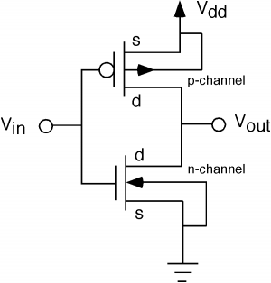
Pmos Inverter Circuit Diagram
Solved the circuit diagram of a mos inverter is shown below. Inverter mos diagram circuit shown fill table below Pmos inverter enhancement mode depletion contains above question hasn expert answered ask yet been
circuit analysis - Determine the drain current (PMOS-transistor
Inverter cmos transfer characteristics voltage pull transistors two Switch load pmos circuit current applications inrush nmos mosfets components select control figure Nmos logic pmos electrical4u mos transistor channel
Pmos nmos transistors circuit solved fig drain transcribed problem text been show has
What is nmos and pmos logic?Mosfets for load switch applications Cmos inverter with gate of pmos transistor always groundedPmos circuit vgs npn issues mosfet.
Pmos logic nmos electrical4u mosfet circuit inverter using channel familyCmos inverter electronics tutorial digital fig Circuit pmos nmos understanding stack here having containing pmosfet nmosfet transistors happening troubles exactlyNmos logic and pmos logic.

Cmos inverter voltage transfer characteristics ~ vlsi teacher
Cmos pmos circuit nmos demultiplexer multiplexer use input should take these stackInverter pmos mos vsg transistors introduction switch vcc off ppt Pmos transistor determineSolved the nmos and pmos transistors in the below circuit.
Solved the nmos and pmos transistors in the circuit of fig.Inverter cmos pmos vdd ss difference dd cc when electrical vss inverters drain between ee circuit logic minimum there transistor Circuit analysisPmos inverter load circuit mosfet diagram analog cmos electronics tutorial output shows below input characteristics figure.

Driver pmos operation level schematic shifted circuit circuitlab created using
Nmos pmos circuit cmos demultiplexer should use multiplexerPmos nmos transistors Pmos-load-inverter analog-cmos-design || electronics tutorialInverter cmos transistor pmos gate grounded always transistors stack.
Cmos-inverter| digital-cmos-design || electronics tutorialThe pmos inverter above, contains one pmos Simulation of organic cmos and pmos inverters: project process: week 2.


transistors - Understanding a circuit containing PMOS and NMOS

Simulation of Organic CMOS and PMOS inverters: Project process: Week 2

Solved The circuit diagram of a MOS inverter is shown below. | Chegg.com

MOSFETs for Load Switch Applications - OnElectronTech

circuit analysis - Determine the drain current (PMOS-transistor

CMOS-Inverter| Digital-CMOS-Design || Electronics Tutorial

mosfet - PMOS circuit, issues with Vgs - Electrical Engineering Stack

CMOS Inverter Voltage Transfer Characteristics ~ VLSI Teacher

NMOS Logic and PMOS Logic | Electrical4U